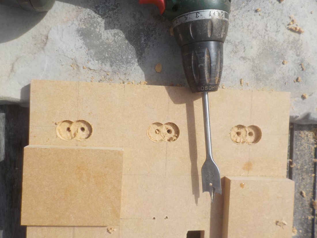
In this final experiment development process I will be trying to combine a lot of different skills and practiced circuits to make my Laser Tag DartBoard. In fact I use almost every available interface on the Arduino Leonardo. For example, I use both 3.3V, 5V and both ground pins. Every serial analogue entry pin A0 – A5 and all but one of the digital pins from 1-13. I actually made the mistake of making a dart board that had room for 8 targets and drilled the holes but cannot use them because I have used all of the available space on my Arduino.
Hopefully my work will be a success as I have no reason to believe that it won’t be.
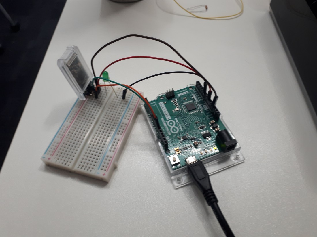
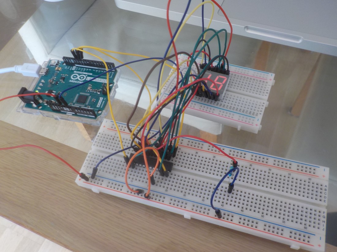
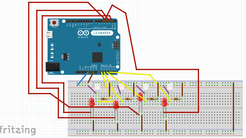
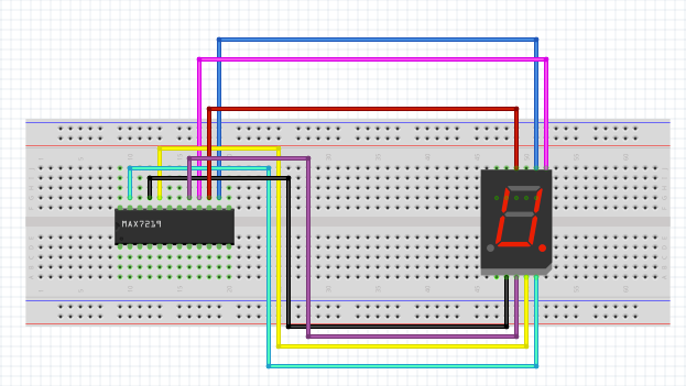
First of all I am going to attempt to make a practice circuit without attaching it to the wooden dart board I have made. I made a circuit that looks very complicated like this…
It has been hard to make and I have had to buy many more jumper wires than I had to get enough to make it. I’m glad I bought two Maxim 7219’s because it would have been very difficult without them. This time I set up the full 6 targets to test and both the score and countdown timer.
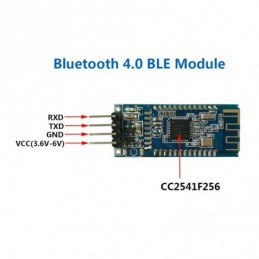
It all seemed to be going well until as I tried to make it work I found it would not display the led to target for more than a split second. After fiddling with different things and checking all the wiring, connections and my code I realised that the countdown clock was still working. This seemed to be relevant.
The problem was it seems that the code to run the countdown clock was interfering with the rest of the program. It looked like this…
for (int i = 9; i > -1; i–) {
lc.setDigit(0,1,i,false);
for (int j = 9; j > -1; j–) {
lc.setDigit(0,0,j,false);
delay(1000); <=== THIS WAS THE PROBLEM
}
}
The problem was the delay function was halting the progress of the algorithm and using a for loop was resulting in the code only running the countdown and ignoring the rest. I looked around on the internet and found some information that could be a solution such as at https://www.norwegiancreations.com/2017/09/arduino-tutorial-using-millis-instead-of-delay/.
The solution was to use the function millis() which basically counts the time in millisecond since the start of the program. It has other benefits such as that it is never inaccurate the same way delay is because the timing is independent of the rest of the program, i.e you will not take longer because of different code execution. The other improvement is it does not halt the rest of the program to take place, it can run alongside the program without interrupting it. So while abandoning the for loop because it also may interfere with the program by being executed before the program continues I made another code solution using if statements. Like this…
if (tens > 0) {
if (millis() > time_now + period) {
if (single > 0) {
single–;
//tens–;
time_now = millis();
} else {
tens–;
single = 9;
time_now = millis();
}
}
} else if (tens == 0 && single > 0) {
if(millis() > time_now + period) {
tens = 0;
single–;
time_now = millis();
}
} else {
tens = 0;
single = 0;
stopFlag = true;
}
This code basically stores values and whenever the time in milliseconds is above 1000 it make an iteration to decrease a number by -1. The slightly more complicated part is catching when the clock for seconds has reached zero. Which could work but will actually try to count below zero.
having found I needed to fix a problem to make the last 9 seconds where the tens value is 0 but the seconds value is 9-0. I improve the whole program by adding a boolean for the whole game to end called stopFlag. Which will stop the game at 00 and leave the score visible while the player cannot continue to gain points. So problem solved.
The code of the whole final experiment looks like this…
#include <LedControl.h>
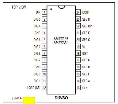
LedControl lc=LedControl(13,12,11,1); // (DIN, CLK, LOAD, number of Max7219 chips)
LedControl ld=LedControl(10,9,8,1); // (DIN, CLK, LOAD, number of Max7219 chips)
int target; // a number that decides which target sensor in the witch is activated
int score; // the number of points scored in 1-9
int Tscore; // the number of points in tens scored
bool stopFlag; // a boolean used to know when the game has ended
long time_now; // a dynamic number that is updated to measure a second
int period; // a number of a thousand to account for a second
int tens; // the value used to display the tens of the timer
int single; // the value used to display the seconds of the timer
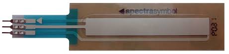
int sensorPin1 = A0; // select the input pin for phototransistor
int sensorPin2 = A1; // select the input pin for phototransistor
int sensorPin3 = A2; // select the input pin for phototransistor
int sensorPin4 = A3; // select the input pin for phototransistor
int sensorPin5 = A4; // select the input pin for phototransistor
int sensorPin6 = A5; // select the input pin for phototransistor
int sensorValue1 = 0; // variable to store the value coming from the sensor
int sensorValue2 = 0; // variable to store the value coming from the sensor
int sensorValue3 = 0; // variable to store the value coming from the sensor
int sensorValue4 = 0; // variable to store the value coming from the sensor
int sensorValue5 = 0; // variable to store the value coming from the sensor
int sensorValue6 = 0; // variable to store the value coming from the sensor
void setup() {
lc.shutdown(0,false); // Wake up MAX7219
lc.setIntensity(0,7); // Set brightness to medium
lc.clearDisplay(0); // Clear all displays connected to MAX7219 chip #
lc.setDigit(0,0,0,false); // (Max7219 chip #, Digit, value, DP on or off)
lc.setDigit(0,1,0,false);
ld.shutdown(0,false); // Wake up MAX7219
ld.setIntensity(0,7); // Set brightness to medium
ld.clearDisplay(0); // Clear all displays connected to MAX7219 chip #
ld.setDigit(0,0,0,false); // (Max7219 chip #, Digit, value, DP on or off)
ld.setDigit(0,1,0,false);
pinMode(1, OUTPUT); // sets up the pins at outputs
pinMode(2, OUTPUT);
pinMode(3, OUTPUT);
pinMode(4, OUTPUT);
pinMode(5, OUTPUT);
pinMode(6, OUTPUT);
digitalWrite(1, LOW); // start all pins as low output
digitalWrite(2, LOW);
digitalWrite(3, LOW);
digitalWrite(4, LOW);
digitalWrite(5, LOW);
digitalWrite(6, LOW);
target = 1; // default start the game at target 1
score = 0; // starts score at one
Tscore = 0; // start 10 score at 0
period = 1000; // assigns a vlaue of thousand millis for a second
time_now = 0; // sets time now at zero
tens = 9; // start timer with a nine
single = 9; // start timer with a nine
stopFlag = false; // stops the game from ending too soon
}
void loop() {
//Serial.println(“In the Loop!!”);
//Serial.println(target);
while (stopFlag == false) {
switch (target) {
case 1:
Serial.println(“Sensor1 Active”); // a comment that helps test the code
digitalWrite(1, HIGH); // sets the LED at high / turns it on
sensorValue1 = analogRead(sensorPin1); // read the value from the sensor
Serial.println(sensorValue1); // prints out the value so I can check it is working
if (sensorValue1 > 4) { // if the sensor picks up a value higher than 4
Serial.println(“Sensor1 Hit!!”); // comment that tells me the sensor was hit
digitalWrite(1, LOW); // after being hit the LED is turned of
score++; // increments score to update the game
delay(300); // gives a small delay before the game continues
target = getTarget(); // call function to get random target
}
break;
case 2:
Serial.println(“Sensor2 Active”);
digitalWrite(2, HIGH);
sensorValue2 = analogRead(sensorPin2); // read the value from the sensor
Serial.println(sensorValue2);
if (sensorValue2 > 4) {
Serial.println(“Sensor2 Hit!!”);
digitalWrite(2, LOW);
score++;
delay(300);
target = getTarget();
}
break;
case 3:
Serial.println(“Sensor3 Active”);
digitalWrite(3, HIGH);
sensorValue3 = analogRead(sensorPin3); // read the value from the sensor
Serial.println(sensorValue3);
if (sensorValue3 > 4) {
Serial.println(“Sensor3 Hit!!”);
digitalWrite(3, LOW);
score++;
delay(300);
target = getTarget();
}
break;
case 4:
Serial.println(“Sensor4 Active”);
digitalWrite(4, HIGH);
sensorValue4 = analogRead(sensorPin4); // read the value from the sensor
Serial.println(sensorValue4);
if (sensorValue4 > 4) {
Serial.println(“Sensor4 Hit!!”);
digitalWrite(4, LOW);
score++;
delay(300);
target = getTarget();
}
break;
case 5:
Serial.println(“Sensor5 Active”);
digitalWrite(5, HIGH);
sensorValue5 = analogRead(sensorPin5); // read the value from the sensor
Serial.println(sensorValue5);
if (sensorValue5 > 4) {
Serial.println(“Sensor5 Hit!!”);
digitalWrite(5, LOW);
score++;
delay(300);
target = getTarget();
}
break;
case 6:
Serial.println(“Sensor6 Active”);
digitalWrite(6, HIGH);
sensorValue6 = analogRead(sensorPin6); // read the value from the sensor
Serial.println(sensorValue6);
if (sensorValue6 > 4) {
Serial.println(“Sensor6 Hit!!”);
digitalWrite(6, LOW);
score++;
delay(300);
target = getTarget();
}
break;
}
lc.setDigit(0,0,score,false); // calls one side of Led display to display score in single digits
lc.setDigit(0,1,Tscore,false); // calls one side of Led display to display score in double digits
if (score > 9) { // if score is above nine +1 to the tens
Tscore++; // increments the tens score
score = 0; // resets score single digits to 0
}
ld.setDigit(0,1,tens,false); // prints the count in tens
ld.setDigit(0,0,single,false); // prints the count of single digits
if (tens > 0) { // if number of ten digits is still above zero
if (millis() > time_now + period) { // if time plus 10 seconds has been exceeded
if (single > 0) { // if score not zero
single–; // decrease time by one second
//tens–;
time_now = millis(); // the time_now variabe is reset to count another second
} else {
tens–; // decrease number of tens digit by one
single = 9; // reset the single digit to 9
time_now = millis(); // the time_now variabe is reset to count another second
}
}
} else if (tens == 0 && single > 0) { // an else if for the last 9 seconds below ten
if(millis() > time_now + period) { // if a second has passed do this
tens = 0; // tens stays at 0
single–; // single digits continues to decrease
time_now = millis(); // the time_now variabe is reset to count another second
}
} else {
tens = 0; // if time runs out
single = 0;
stopFlag = true; // a bool that causes the end of the game
}
delay(100); // a little delay for stability
}
}
int getTarget() { // function used to choose next target
int counter = random(1,7); // a int counter and a random number from 1-6
return counter; // returns the number
}
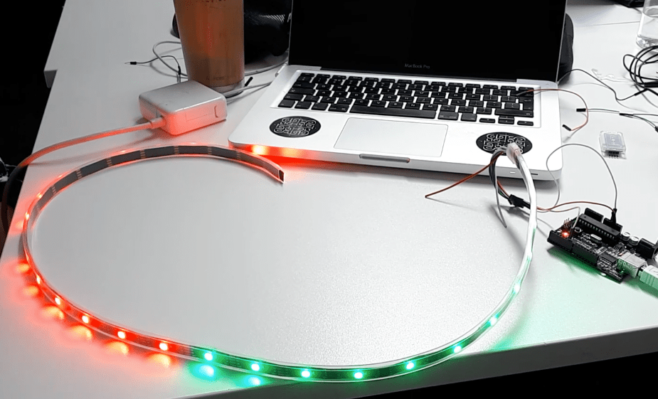
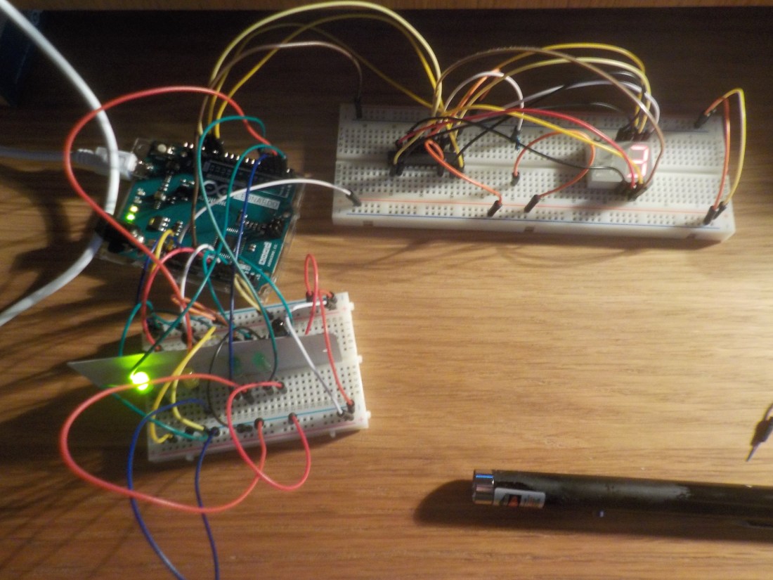
The next objective is to recreate all of this on the actual dartboard I have made. Some of the tools I used for this are sticky back velcro and insulated tape. After securing the Arduino and a bread board I started to make my circuit. Like this…

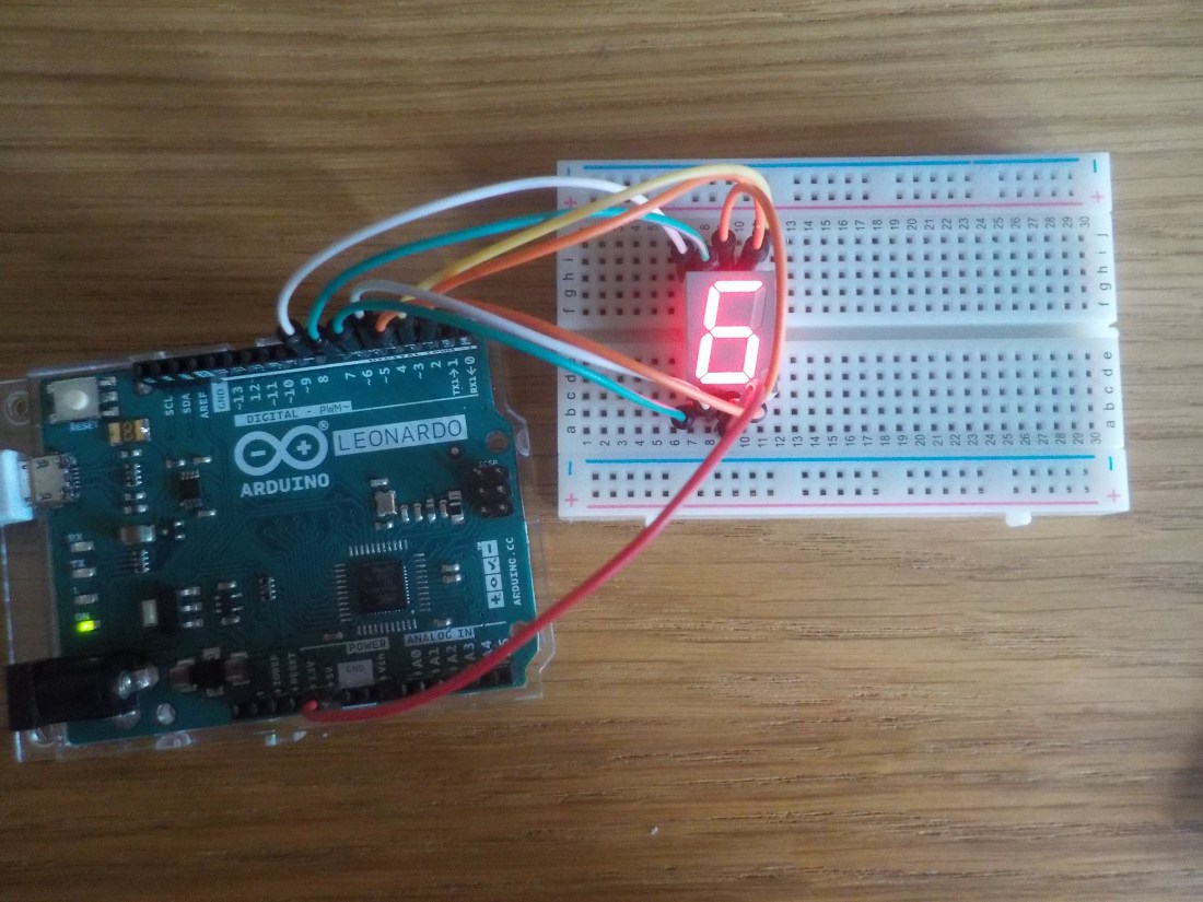
Which is one chip and one 7 segment display working. Then I progressed to making a circuit where both 7 segment were working, like this…

The problem I found when testing this is that I succeeded in every way finding the correct pins and printing the timer/score. But that I was left with the numbers backwards having secured the connections with the board face down. So painstakingly I reconnected the pins moving counterclockwise and the result looked like this…
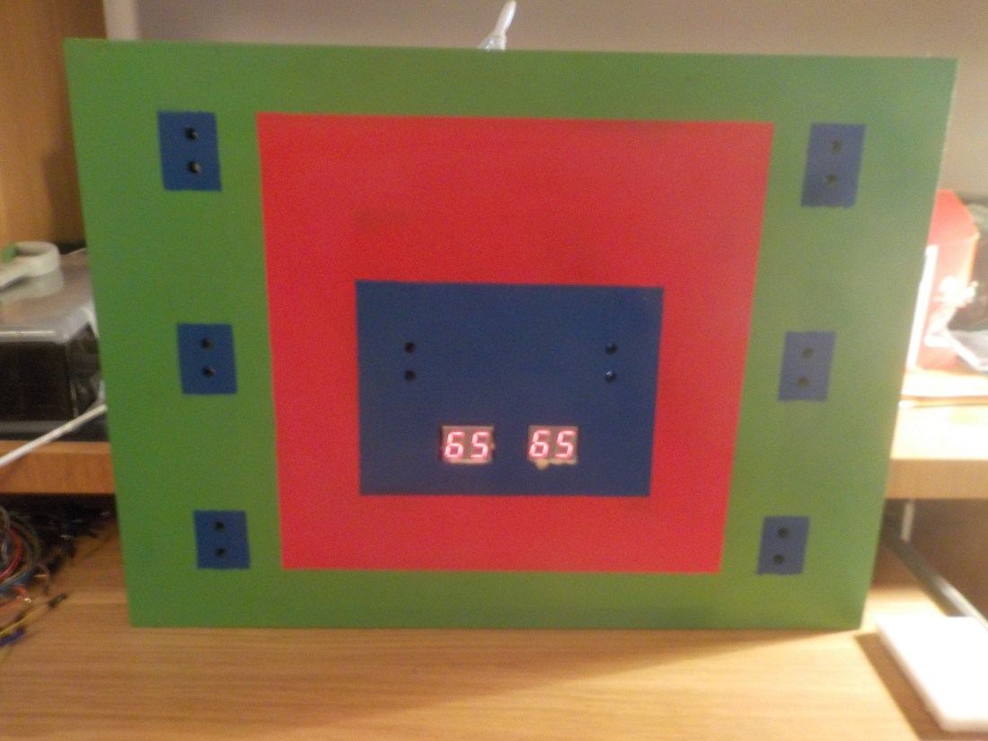
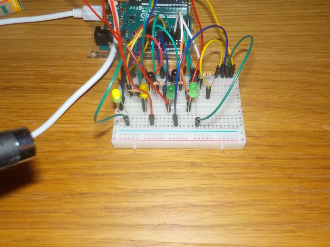
From here I used BlueTac to fill all the holes I would be using to push anode and cathode wires through and to make the LEDs and sensors keep their position. I added to the circuit with all the connections between sensors and LEDs fastened securely with blue insulated tape.
It was important when making these connection to have lots of male-male, male-female and female-female jumper wires. These enable you to use female ends to connect firmly to the wires of LEDs etc. Sometimes a female to female can be used with male-male wires added either side. But this can be worked out as you put the circuit together. It is very handy to have an excess of these wires or your progress might be stunted like mine was at times. So the final circuit looked like this…

I was so pleased to have everything together, all that is left is the moment of truth.


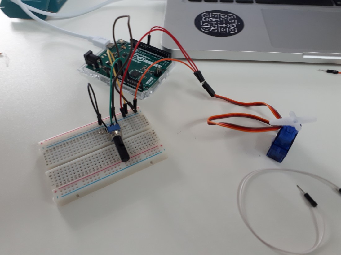
 Using Servos is an interesting opportunity for experimentation because servos can be arranged to perform all kinds of actions and this is the first ability to physically move something I have had learning on this degree course. Here are examples of experiments made using Servos…