Our second week of Physical computing was a step of development to understanding information like Ohm’s Law… (Volts = Current * Resistance).

This physics formula helps to scientifically understand electric current and voltage with relevance to resistance. Resistance is important for creating circuits while using an Arduino, where we use resistors to limit the voltage pushed through by current that can affect our components. Such as blowing an LED and breaking it. If you didn’t know this is what a resistor looks like on our small circuits.
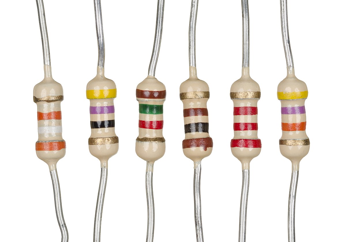
Its important to understand the range of resistors and their values. For example I typically use 100ohm resistors in my circuits. But there are resistors with values ranging from 100’s of ohms to kilo ohms (1000) to milli ohms (1,000,000). To identify the values of a resistor that is fit for your purpose you use colour code bands like the ones shown above.
The colours of the 1st and 2nd band create a number such as green (5) blue (6) resulting in 56 multiplied by yellow (10k) with a tolerance of gold (+ or – 5%).

Reading resistance values can be difficult at times such as knowing which end of the resistor is the 1st band or tolerance but there are some methods to working out the value. Similar to above there may be a gap between the last and second last band. Sometimes the 1st band is closer to a lead. You can also tell with some certainty that a band is tolerance or band value based on colours like gold and silver which only have multiplier and tolerance values. Or bands like orange, yellow and white which are never tolerance.
Within the class we looked at the use of an interesting component, an LDR or Light Dependant Resistor which only costs 60p. It is an interesting bit of kit that detects light and the more light the higher the resistance created by the LDR. I used this code to test for the presence of light and record values for resistance across a circuit using the LDR…
int sensorPin = A0; // select the input pin for LDR
int sensorValue = 0; // variable to store the value coming from the sensor
void setup() {
Serial.begin(9600); //sets serial port for communication
}
void loop() {
sensorValue = analogRead(sensorPin); // read the value from the sensor
Serial.println(sensorValue); //prints the values coming from the sensor on the screen
delay(100);
}
The circuit I used was the same as this one I found online…
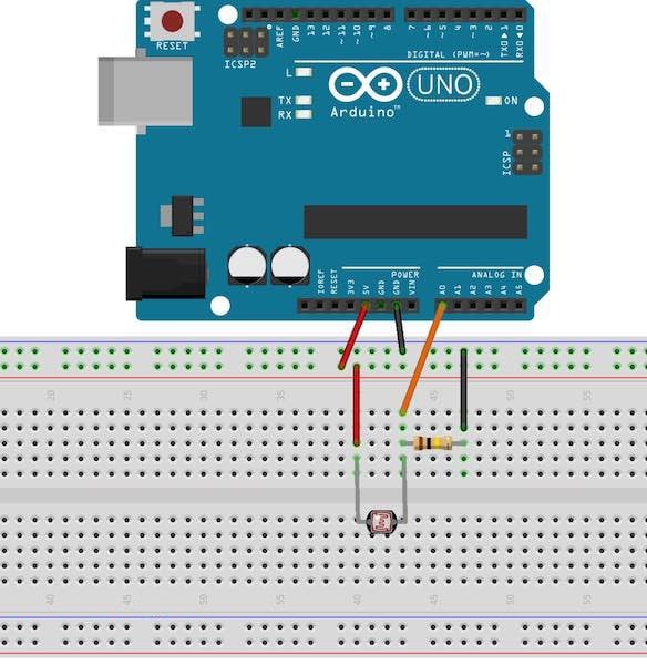
And this was my circuit…

This is a copy of some of the values I recorded while interacting with the LDR by covering it with my hand and letting it receive light…
42,42,42,207,220,223,221,222,223,222,221,200,154,143,77,41
This Lead me to an idea for an experiment where I code use light detecting components to create a ‘laser tag’ dartboard where you shoot sensors on a dartboard. So I did some research about homemade laser tag and the components I would need to create it. This website was helpful…
https://www.instructables.com/id/Duino-Tagger/
It has a list of necessary items to create the laser tag Arduino project:
Arduino
Light Gun
Coloured LED’s (preferably 30mA+)
IR sensors
At least 2x IR LED’s matched to the IR receiver (preferably 100mA+)
Peizo sounder
Power transistor /MOSFET
A few electronics basics: solder, resistors , capacitors.
You may also want
Scrap plastic
LED bar graph driver chips
More LED’s
Record your own message greetings card
Hats / helmets / headbands to mount sensors on
Because of this list I bought a laser tag system


