The start of my development meant getting a bit ahead of myself and trying to make the actual dart board to house all the components, Arduino and breadboards. Which started by a trip to B&Q where I bought some wood and had it cut for the price of a £2 charity donation.
I set to work marking out the holes to drill to find the spaces where I could fit panels to be the backbone of the board. Or something to set up a hook and hand the board from. Then once I knew the positions I wanted pieces in I glued them down using gorilla glue.

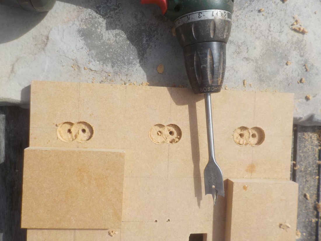
I then drilled holes in the board. One hole slightly above the other a total of 8 times. This was because I would need to have a hole for the led target and the phototransistor just below. I also had to make the LED’s sit slightly inside a lip so the light didn’t reach the sensor target.
I did this by drilling a small 2ml hole all the way through to act as a guide for other drilling. Then a 6ml hole less than a centimetre in on the LED hole to act as a base for the LED to rest on. On the other Side I used a spade point to clear an area behind the LEDs and sensor so I had more room to work with the anode and cathode wires that were exposed out the back.
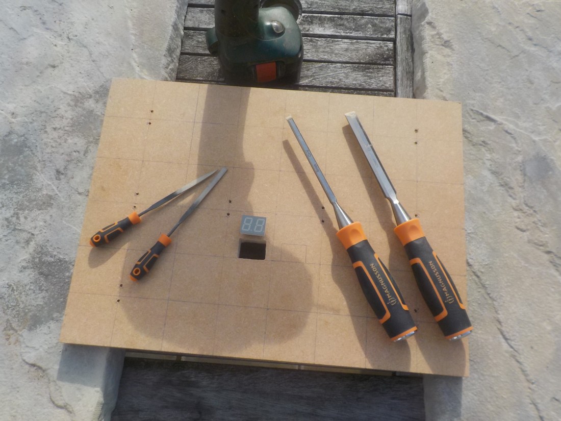
I also made two square holes for the score and countdown timer, by drilling lots of small holes and chiselling out the inside. Using a set of small files to smooth out the inside.
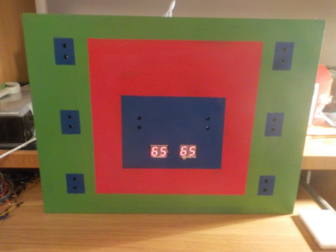
After all holes had been made and the support back bone of the board were complete I used several coats of spray paint to create a more interesting and finished look to the board. So that it ended up like this which you can see from a photo I took having added the 7 segment displays using super glue.
The next step for development was to build a circuit which used a combination of things I had made along the way and to add the score board. I did this by combining work with 7 segment display and the photo sensor circuit I made earlier. The end result looked like this…
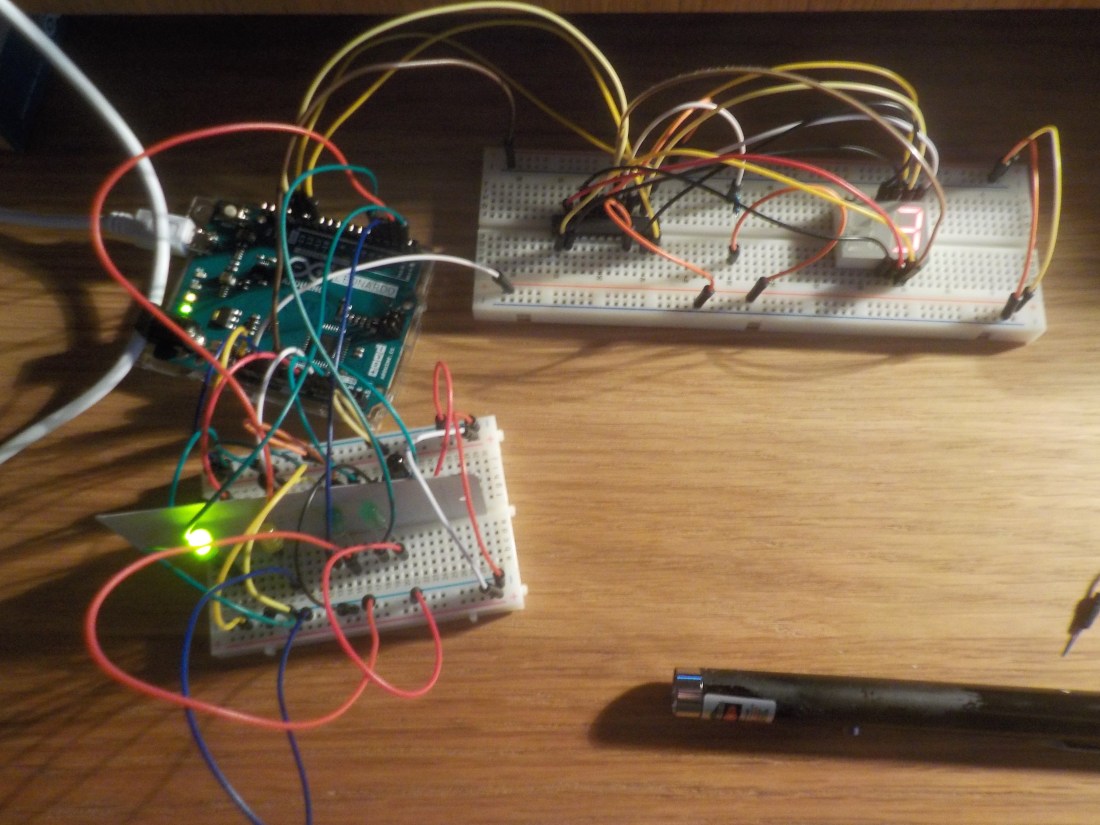
As you can see the score has reached 3 from shining the laser pointer at the correct target. The circuit looks like this…

This does not complete the circuit, I have left out all the connections that go from the chip to the 7 Segment display because it is too complicated to see in such a small space but the additional connections needed are these…
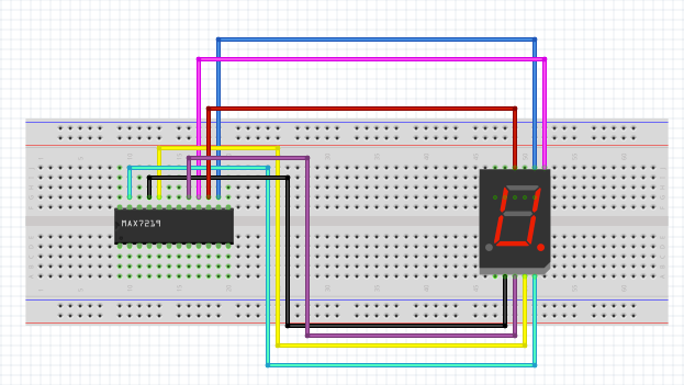
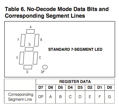
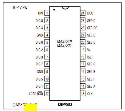
This structure will have to be repeated for each side of the 7 segment display. But I cannot create a diagram for something that complex and the tool that I used to draw it does not contain Dual Led Displays. You have to use the previous circuit and then use the corresponding pin on the Maxim 7219 from A-F to move around the the Display using A-F for one digit on the left and right side.
To best be able to wire the circuit with a driver chip correctly use these two diagrams (below) to know where the pins from A-F are and relate them to a visual confirmation that you have found the right pin on the Dual Display. Easiest done by setting up a code program that constantly draws and 8 on the displays or using individual Arduino pins to confirm you have the right display pin. If you use a common cathode display, like I have, you will need to ground the display, but with a chip it is grounded while connected to the chip as long as the chip is grounded correctly.
With my circuit working including a score I’m happy to progress more with the prototyping and get closer to the final result of experimentation.
