My goal for the final experiment is to create a Laser Tag Dart board game with a score and count down timer. These are the parts I have Bought so far to complete the project

I bought these parts from Farnell.com. It includes 7 Segment LED displays, single (top-middle) and dual (right). To display scores and a countdown. There are 2 types of phototransistor (bottom middle). Two LED display driver chips (top-left) and Lots of LEDS in green and red colour (bottom-left).
The first experiment I did was with the phototransistor, using a circuit like this…
And code like this (left) to get readings like this (right) …


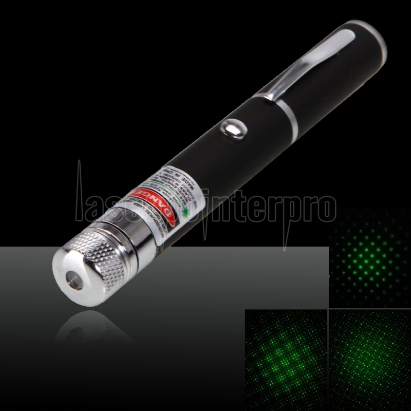
To get the reading I shone a light up close to the phototransistor and it worked!! The benefit of the phototransistors I was using is they are dim to cancel out low light. The same experiments with the other clear resistors was that they were receiving natural light and only giving resistance readings between 0 and 8. These dimmed transistors and high sensor values should work perfectly. In the actual experiment I will use a laser pointer because while testing the little guns I had they did not get a reading. This is the laser pointer I have purchased at a low price with 97% off…
Now that I have the laser pointer I moved on to testing the circuit with it. The problem was I wasn’t getting a high enough reading to cause a sensor hit. With the preferred dimmed phototransistor I was getting a 0-4 score of resistance when expecting around 200 as shown by my code. While trying with the low value clear transistor I didn’t get a reading at all.


I had to try this from a distance and in the dark to see if I could register as low a resistance value as 4 to get a hit. In a dark room and at some distance I was getting readings as high as 40 which could work. I found it added to the drama to be using the laser pointer in the dark. It was a foreseen problem and part of my original intentions but I was so overconfident about my work at that point. It seems now that I will be able to make a working prototype and that it be hard enough to be fun to play with.
Another experiment I was working with involved two different 7 segment LED displays to work as the clock counting either up to or down from 99. Another Led display to count the score. The first thing I tried to get working was a counting clock with a single 7 segment. It was fairly simple in the end but I had to use some guidance from resources online.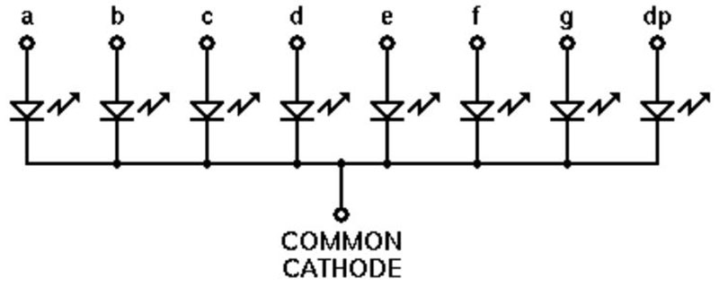
This diagram shows the internal structure of a common cathode 7 Segment LED display. There are two types of 7 Segment display, common cathode and common anode. The difference between them involves the position of power and ground to complete the circuit where polarity is different as resistors appear in different places. Like this…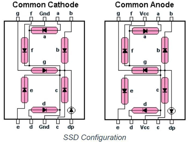
On the common cathode 7 segment display you must connect the nodes that say ground (GND) to ground to complete the circuit. A set up of the circuit for the single LED display is based on something like this…

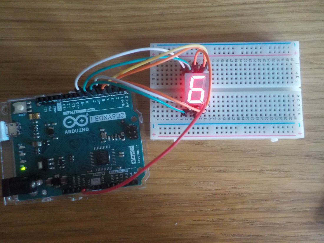
This was simple but requires you to commit to memory a basic knowledge of these circuits. As in the diagram above, the segments appear in order A-F they must be plugged into the Arduino nodes in ascending order. This is because there is an array created to switch on LEDs in the display corresponding to each segment that makes up numbers 0-9. It is also handily possible to create the letters H-E-L-P should it ever be necessary. This is the code I used to make the display count down from 9-0 repeatedly…

The num_array at the top is the list of values for each number 0-9 to appear such as 0 which is 1,1,1,1,1,1,0 leaving just the middle section out of the 7 segment. Every time the num_Write function is called it cycles through the pins and gives them a binary value of 0/1 or low and high to turn them on. Each new number either gives a high value or sets them to 0 or low. The 400 millisecond delay is there to put a pace of nearly a second on each different number appearing. This is what it looked like complete…
With these two experiments complete I have some of the groundwork for my final experiment. But I need to build on these to make each of the parts of my Laser Tag Dart Board.
Next I worked on setting up a dual 7 segment display which helps me get into double digits for either the score or the timer. The problem is having tested the working pins on the Arduino showing that the pin 0 does not work that means pins 1-13 are the only ones I can use. But a dual seven segment display needs 14 pins to power each of the LEDs. Therefore the most I could do is power all but one LED on the dual display like this…

While testing this and other 7 segment display it proved useful as I found displays that has become dysfunctional such as this one where two of the LED have short circuited where one pin powers 2 LEDs, like this…

Because I cannot power a whole dual seven segment or even the desired 2 dual 7 segment I have to use a driver chip. Here is the driver chip I am using
It is a MAXIM 7219, and I have two of them. They are especially useful for my experiment because I can use only 3 pins and power a whole dual 7 segment LED display.
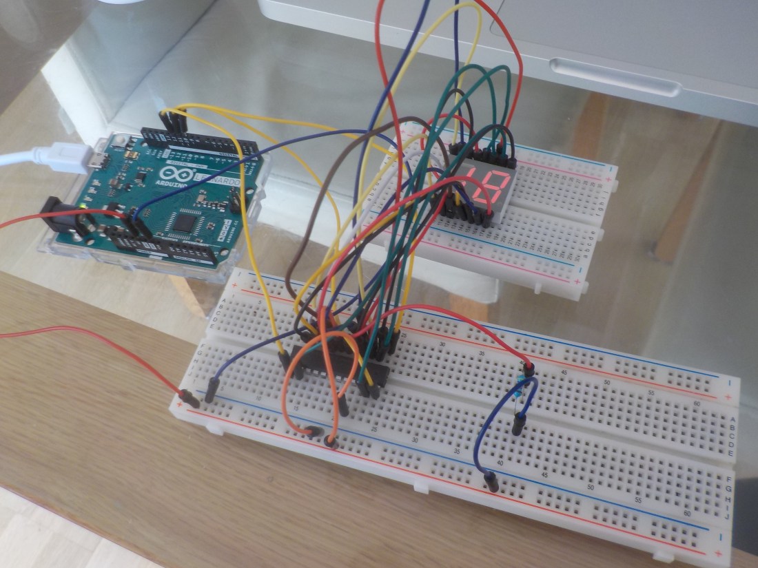
To help me understand how to wire a circuit for a dual 7 segment display I used the site https://www.brainy-bits.com/using-7-segment-display-with-arduino/ . There is lots of information about all the components and how to wire with 7 segment displays. It was also useful that the tutorial is made using the same MAXIM 7219 driver chips that I am. This is the circuit I used to wire my Dual LED display with a driver chip.

In my circuit I didn’t use two led displays I just stuck to the one and for the time being. Here is an image of what I made…
This is a dual 7 segment display counting down from 99 to zero using this code…

It is important to note that there is a library installed to make this work called LEDControl. Which is available here… https://www.arduinolibraries.info/libraries/led-control . Once its downloaded you can access it in the Arduino interface. Open Arduino and go to Sketch – include library – Led Control. Like this…

With the library included reference it using the code line
#include <LedControl.h> an then create an instance with the line
LedControl lc = LedControl(13, 12,11,1). This code references the three pins I will be using to power the driver chip and the last 1 means the number of chips I will be using. This is because a driver chip can be used to create a matrix and power up to eight seven segment display or 64 individual LEDs. But also driver chips can be used in a matrix where many driver chips power huge array of LEDs.
An example of this using some similar technology is in Times Square in New York where the huge screen are made with matrixes of LEDs using RGB colour codes. So essentially a driver chip is the beginning of the technology that brings the bright lights of Times Square.
To further prepare for the final experiment I created a phototransistor circuit. To see what difficulty might come from multiple transistors and LEDs sequenced to get hits. Which would require an LED relevant to each transistor and there would have to be random jumps from one target/Led to another. This is what I made…
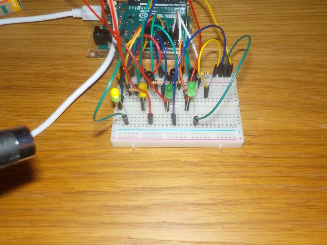
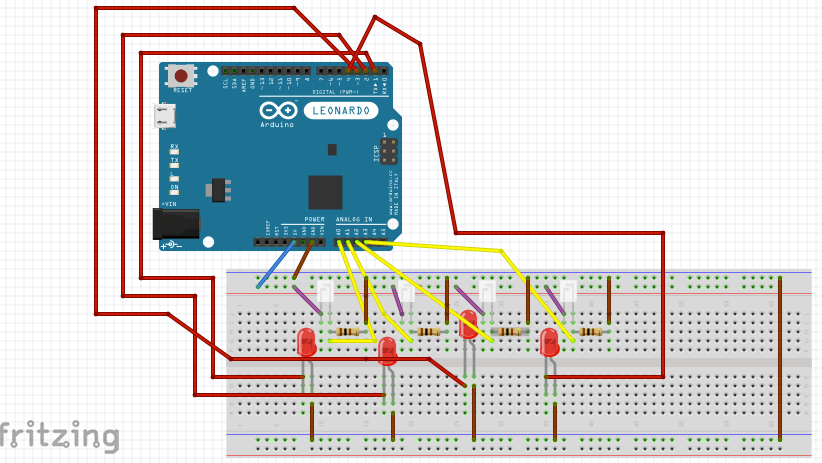
Here are 4 target transistors and 4 LEDs that correspond to them, I actually separated LEDs and transistor with a bookmark because I found that the light from the LED next to its transistor would actually trigger the hit sometimes. This was a relatively simple circuit to make and all based on simpler circuits but some knowledge was needed to apply to this exact situation. Here is a circuit diagram to understand…
Using this code I wrote I was able to shine a laser at each phototransistor target corresponding to a lite up LED. Like this…
int target;
int sensorPin1 = A0; // select the input pin for phototransistor
int sensorPin2 = A1; // select the input pin for phototransistor
int sensorPin3 = A2; // select the input pin for phototransistor
int sensorPin4 = A3; // select the input pin for phototransistor
int sensorValue1 = 0; // variable to store the value coming from the sensor
int sensorValue2 = 0; // variable to store the value coming from the sensor
int sensorValue3 = 0; // variable to store the value coming from the sensor
int sensorValue4 = 0; // variable to store the value coming from the sensor
void setup() {
//Serial.begin(9600); //sets serial port for communication
target = 1;
pinMode(1, OUTPUT);
pinMode(2, OUTPUT);
pinMode(3, OUTPUT);
pinMode(4, OUTPUT);
//target = getTarget();
//Serial.println(“program started”);
}
void loop() {
//Serial.println(“in the loop”);
//Serial.println(target);
//target = getTarget();
//target = 1;
switch (target) {
case 1:
Serial.println(“Sensor1 Active”);
digitalWrite(1, HIGH);
sensorValue1 = analogRead(sensorPin1); // read the value from the sensor
Serial.println(sensorValue1);
if (sensorValue1 > 10) {
Serial.println(“Sensor1 Hit!!”);
Serial.println(sensorValue1);
digitalWrite(1, LOW);
delay(400);
target = getTarget();
}
break;
case 2:
Serial.println(“Sensor2 Active”);
digitalWrite(2, HIGH);
sensorValue2 = analogRead(sensorPin2); // read the value from the sensor
Serial.println(sensorValue2);
if (sensorValue2 > 10) {
Serial.println(“Sensor2 Hit!!”);
Serial.println(sensorValue2);
digitalWrite(2, LOW);
delay(400);
target = getTarget();
}
break;
case 3:
Serial.println(“Sensor3 Active”);
digitalWrite(3, HIGH);
sensorValue3 = analogRead(sensorPin3); // read the value from the sensor
Serial.println(sensorValue3);
if (sensorValue3 > 10) {
Serial.println(“Sensor3 Hit!!”);
digitalWrite(3, LOW);
delay(400);
target = getTarget();
}
break;
case 4:
Serial.println(“Sensor4 Active”);
digitalWrite(4, HIGH);
sensorValue4 = analogRead(sensorPin4); // read the value from the sensor
Serial.println(sensorValue4);
if (sensorValue4 > 10) {
Serial.println(“Sensor4 Hit!!”);
digitalWrite(4, LOW);
delay(400);
target = getTarget();
}
break;
}
delay(200);
}
int getTarget() {
int counter = random(1,5);
return counter;
}
This code uses a switch in the loop to access each target and turn the light on, starting with target 1 which is defined in the setup loop. There is a function called getTarget which creates a random number between 1 and less than 5. It all works.
Now I think I’m ready to make more complicated experiments combining the things I’ve learnt.
